Operation of the Varian Turbo Pumping Station
SD40 Mechanical Pump
And Turbo-V70 D
![]() Mechanical Pump Considerations
Mechanical Pump Considerations
![]() Normal Turbo Pump Operating Procedure
Normal Turbo Pump Operating Procedure
Mechanical Pump Considerations
• Oil Temperature: before starting oil temp. must be >15°C.
• Ambient Temp: 10-40°C.
• If Pump has Not been operated recently:
1. To remove vapors and condensates from the pump oil the following procedure should be followed.
2. Blank off inlet to turbo pump.
3. Start pump (see instructions below).
4. If oil is cloudy or contaminated make sure that the mechanical pump has actually started, that is, rotating to prevent electrical damage.
5. Run pump for one hour (yes, the turbo will be operating also)
6. Operate pump with gas ballast wide open for ½ hour to one hour to evaporate the condensable products.
7. Close gas ballast to reach ultimate vacuum.
8. Turbo pump should operate fine during this procedure, however, you should monitor the pump operating parameters and stop pump if there are any problems indicated.
• Always:
9. Check pump oil. It should be half way up the watch glass (cold). Make sure it is clear and not contaminated. Do not operate the pump with contaminated oil.
10. Make sure gas ballast is closed for normal operation.
Normal Turbo Pump Operating Procedure
1. Before operation: Make sure that the pump connections to the vacuum system are connected correctly. During operation: Make sure cooling fan on turbo pump is operating.
2. Display should read “Ready for Local/Soft Start” (See picture above)
3. Press the “Start/Stop Reset” pushbutton.
4. The display will read “Soft Start ON/ [n---------]”
5. The flashing box indicates the level of turbo pump spin speed.
6. After the 10 steps are complete, the display will read “Normal Operation/ XX KRPM” where XX is the spin speed.
7. If a high gas load is present at the inlet of the turbo pump, the controller will automatically reduce the spin speed. If the speed is slowed to 1/8 of normal operating speed the display will indicate “High Load/12 XX KRPM”. If the gas load decreases the pump will automatically return to normal operating speed.
8. Low Speed Operation. This is provided for operating the pump at moderately high pressure with high gas throughput. To operate in this mode, press the “Low Speed” pushbutton. An “LS” will be indicated in the lower right corner of the display. If Low Speed is selected before start up, the pump will first accelerate to normal speed and then slow down to low speed. Low speed is 2/3 of normal spin speed and achieves a higher base pressure than normal operation but with increased throughput.
9. Pump Shutdown. Press the “Start/Stop Reset” pushbutton.
10. Power failure. The controller will stop the turbo and restart it in a normal sequence.
11. To monitor the turbo operating parameters press the “Pump Current/Temperature Time/Power” pushbutton.
Error Messages.
Display: “Fault: / Overtime: S X”
Reason: Pump did not reach desired spin speed in time. X is step number where fault was produced.
Remedy: Check the system for leaks. Press the “Start/Stop Reset” button twice to restart pump.
• Display: “Fault: Pump / Overtemp.”
Reason: Turbo pump bearing temperature has exceeded maximum allowable (60°C).
Remedy: Wait for pump to cool. Try to identify reason for high temperature, check for leaks. Press the “Start/Stop Reset” button twice to restart pump. Note: pump will not restart until temperature is below threshold.
• Display “Fault: Controller/ Over temperature”
Reason: Controller transformer temperature exceeds 90°C.
Remedy: Wait for controller to cool. Try to identify reason for high temperature, check for leaks. Press the “Start/Stop Reset” button twice to restart pump. Note: pump will not restart until temperature is below threshold.
Vacuum Components of Cryo RF
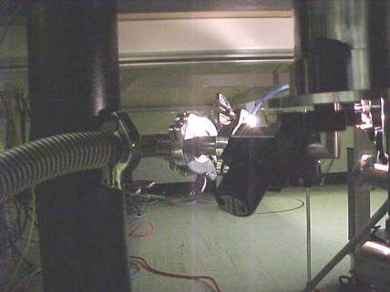
The Cryo RF has a valve on the underside to open the chamber for
pumping. Make sure this valve is open
when you start the pump down. The valve
is shown in the picture below.
There is also an ion gauge, which measures the pressure in the line in front
of this valve. Thus the pressure in the
chamber will be somewhat higher than this reading. The ion gauge is simple to operate. Just turn it on to read the pressure. If the pressure is too high, the gauge will automatically turn
off. There is also a low pressure gauge
to measure the turbo pump’s foreline pressure.


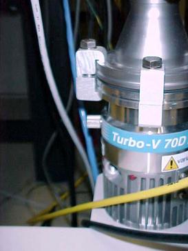
There is a mechanical screw valve on the turbo pump for venting the
system. This screw must only be opened
after the turbo has spun down. The
valve is shown on left side of the pump in the picture below. It is the silver knob in line with the blue
label.